Online Links:
Online Links:
| Range of values | |
|---|---|
| Minimum: | 0 |
| Maximum: | 0 |
| Range of values | |
|---|---|
| Minimum: | 0.2 |
| Maximum: | 4204.5 |
| Units: | meters |
| Range of values | |
|---|---|
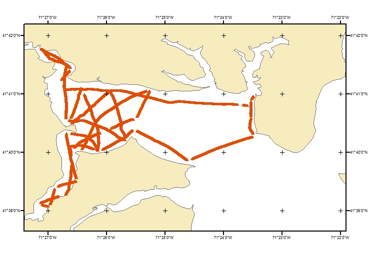
| Minimum: | -71.452099 |
| Maximum: | -71.391345 |
| Units: | decimal degrees |
| Range of values | |
|---|---|
| Minimum: | 41.6512 |
| Maximum: | 41.696261 |
| Units: | decimal degrees |
| Range of values | |
|---|---|
| Minimum: | 295813.8 |
| Maximum: | 300966.8 |
| Units: | meters |
| Range of values | |
|---|---|
| Minimum: | 4613950.2 |
| Maximum: | 4618958.3 |
| Units: | meters |
| Range of values | |
|---|---|
| Minimum: | -12.32 |
| Maximum: | -0.4 |
| Units: | meters |
| Range of values | |
|---|---|
| Minimum: | -11.92 |
| Maximum: | 0 |
| Units: | meters |
| Range of values | |
|---|---|
| Minimum: | 0.1 |
| Maximum: | 99.1678 |
| Units: | ohm-m |
| Range of values | |
|---|---|
| Minimum: | -1 |
| Maximum: | 1.996371 |
| Units: | Log(10) of ohm-m |
| Access_Constraints | None. |
|---|---|
| Use_Constraints | The public domain data from the U.S. Government are freely redistributable with proper metadata and source attribution. Please recognize the U.S. Geological Survey as the originator of the dataset. |
| Data format: | The zip file contains all the point shapefile of the processed CRP resistivity values below the sediment water interace collected on May 14, 2009 from U.S. Geological Survey field activity 2009-021-FA, the data in CSV format, a browse graphic, and the associated metadata files. in format Shapefile (version ArcGIS 9.2) Size: 20 |
|---|---|
| Network links: |
https://cmgds.marine.usgs.gov/data/field-activity-data/2009-021-FA/data/geophysics/shapefile/2009-021-FA_mrgmay14_resbsed.zip https://doi.org/10.5066/F7DR2TSX |
| Data format: | The zip file contains all the point shapefile of the processed CRP resistivity values below the sediment water interace collected on May 14, 2009 from U.S. Geological Survey field activity 2009-021-FA, the data in CSV format, a browse graphic, and the associated metadata files. in format CSV (version ArcGIS 10.3.1/XToolsPro 12.0) comma-separated values Size: 20 |
|---|---|
| Network links: |
https://cmgds.marine.usgs.gov/data/field-activity-data/2009-021-FA/data/geophysics/shapefile/2009-021-FA_mrgmay14_resbsed.zip https://doi.org/10.5066/F7DR2TSX |