PNG formatted images of Multi-channel streamer seismic-reflection profiles collected by the U.S. Geological Survey along the Delmarva Peninsula, MD and VA, 2014

Metadata also available as - [Outline] - [Parseable text] - [XML]

Frequently anticipated questions:


What does this data set describe?

Title:
PNG formatted images of Multi-channel streamer seismic-reflection profiles collected by the U.S. Geological Survey along the Delmarva Peninsula, MD and VA, 2014
Abstract:
The Delmarva Peninsula is a 220-kilometer-long headland, spit, and barrier island complex that was significantly affected by Hurricane Sandy. A U.S. Geological Survey cruise was conducted in the summer of 2014 to map the inner continental shelf of the Delmarva Peninsula using geophysical and sampling techniques to define the geologic framework that governs coastal system evolution at storm-event and longer timescales. Data collected during the 2014 cruise include swath bathymetry, sidescan sonar, chirp and boomer seismic-reflection profiles, acoustic Doppler current profiler, and sample and bottom photograph data. Processed data in raster and vector format are released here for the swath bathymetry, sidescan sonar, and seismic-reflection profiles. More information about the USGS survey conducted as part of the Hurricane Sandy Response-- Geologic Framework and Coastal Vulnerability Study can be found at the project website or on the WHCMSC Field Activity Web pages: https://woodshole.er.usgs.gov/project-pages/delmarva/ and https://cmgds.marine.usgs.gov/fan_info.php?fan=2014-002-FA
  1. How might this data set be cited?
    U.S. Geological Survey, 2015, PNG formatted images of Multi-channel streamer seismic-reflection profiles collected by the U.S. Geological Survey along the Delmarva Peninsula, MD and VA, 2014: data release DOI:10.5066/F7MW2F60, U.S. Geological Survey, Coastal and Marine Geology Program, Woods Hole Coastal and Marine Science Center, Woods Hole, Massachusetts.

    Online Links:

    This is part of the following larger work.

    Pendleton, Elizabeth A., Ackerman, S.D., Baldwin, W.E., Danforth, W.W., Foster, D.S., Thieler, E.R., and Brothers, L.L., 2015, High-resolution geophysical data collected along the Delmarva Peninsula 2014, U.S. Geological Survey Field Activity 2014-002-FA: data release DOI:10.5066/F7MW2F60, U.S. Geological Survey, Reston, VA.

    Online Links:

  2. What geographic area does the data set cover?
    West_Bounding_Coordinate: -75.567453
    East_Bounding_Coordinate: -74.685475
    North_Bounding_Coordinate: 38.417831
    South_Bounding_Coordinate: 37.538758
  3. What does it look like?
    https://cmgds.marine.usgs.gov/data/field-activity-data/2014-002-FA/data/seismics/MCSimages/MCS_image.png (PNG)
    Woods Hole Coastal and Marine Science Center sample MCS image along the Delmarva Peninsula
  4. Does the data set describe conditions during a particular time period?
    Beginning_Date: 18-Jun-2014
    Ending_Date: 27-Jun-2014
    Currentness_Reference:
    ground condition
  5. What is the general form of this data set?
    Geospatial_Data_Presentation_Form: raster digital data
  6. How does the data set represent geographic features?
    1. How are geographic features stored in the data set?
      This is a Raster data set.
    2. What coordinate system is used to represent geographic features?
      Horizontal positions are specified in geographic coordinates, that is, latitude and longitude. Latitudes are given to the nearest 0.000001. Longitudes are given to the nearest 0.000001. Latitude and longitude values are specified in Decimal degrees. The horizontal datum used is D_WGS_1984.
      The ellipsoid used is WGS_1984.
      The semi-major axis of the ellipsoid used is 6378137.000000.
      The flattening of the ellipsoid used is 1/298.257224.
  7. How does the data set describe geographic features?
    Entity_and_Attribute_Overview:
    The PNG images can be hyperlinked to their shapefile location in ArcGIS. The images show two-way travel time (seconds) on the y-axis and distance along profile on the x-axis.
    Entity_and_Attribute_Detail_Citation: U.S. Geological Survey

Who produced the data set?

  1. Who are the originators of the data set? (may include formal authors, digital compilers, and editors)
  2. Who also contributed to the data set?
  3. To whom should users address questions about the data?
    Elizabeth A. Pendleton
    U.S. Geological Survey
    Geologist
    384 Woods Hole Road
    Woods Hole, MA
    USA

    508-548-8700 x2259 (voice)
    508-457-2310 (FAX)
    ependleton@usgs.gov

Why was the data set created?

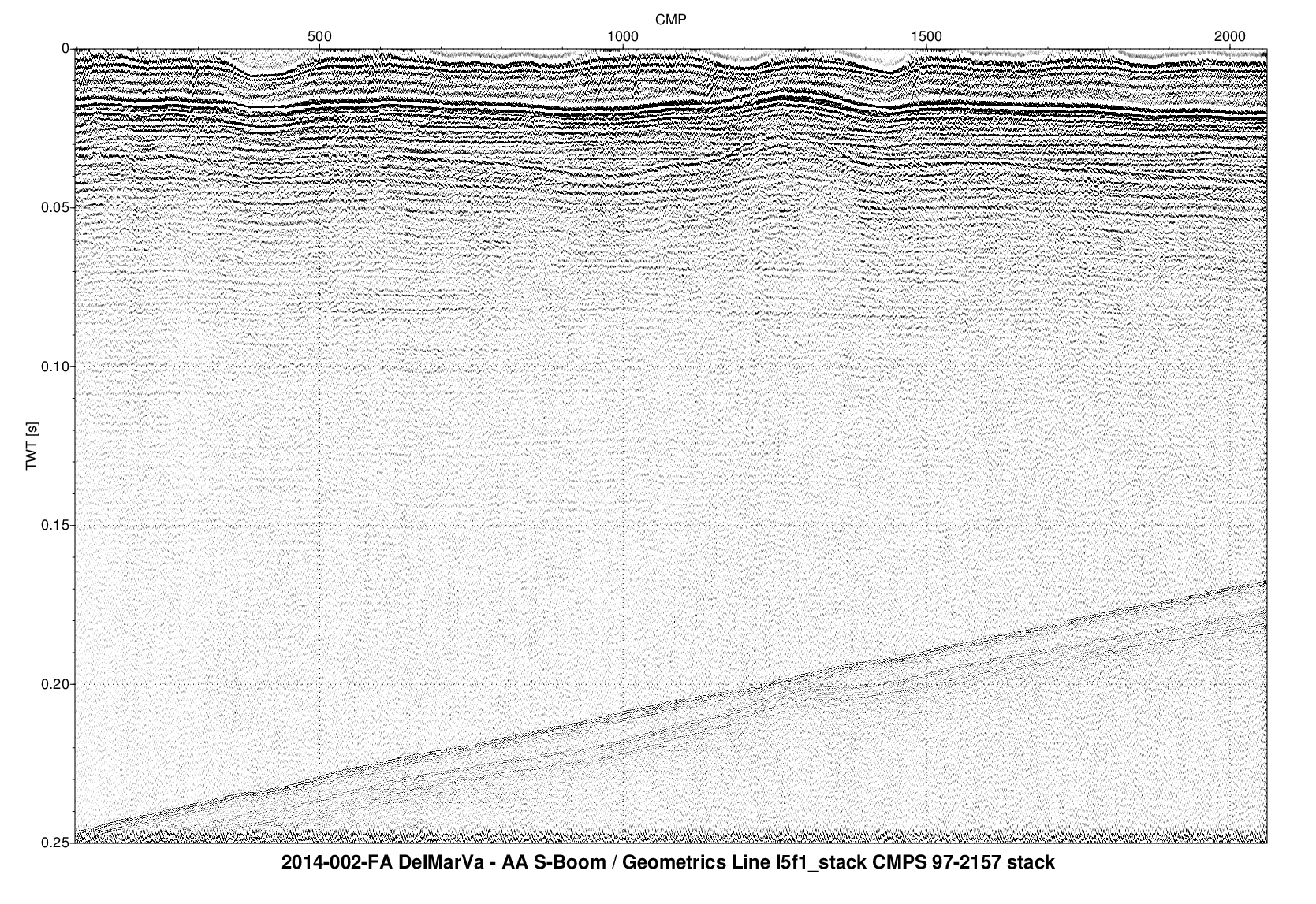
PNG images of each seismic profile were generated in order to incorporate images of the seismic profiles into Geographic Information System (GIS) projects and data archives utilizing HTML. These images represent approximately 1700 km of multi-channel streamer seismic-reflection data collected by the U.S. Geological Survey during cruise 2014-002-FA along the Delmarva Peninsula, MD and VA. Each profile image can be hotlinked to its corresponding trackline navigation contained within the Esri polyline shapefile '2014_002_FA_MCS_Tracklines.shp'. Even 100 reflection point markers along the top of the PNG images correlate to the positions of 100-rp intervals within the Esri point shapefile '2014_002_FA_MCS_rp100.shp'.

How was the data set created?

  1. From what previous works were the data drawn?
    MCS data (source 1 of 1)
    U.S. Geological Survey, Unpublished Material, Raw MCS data.

    Type_of_Source_Media: disc
    Source_Contribution:
    MCS seismic data were collected using S-Boom source and a 100-m long GeoEel 16 channel streamer. The applied acoustics S-Boom source was towed astern of the M/V Scarlet Isabella at a power level between 200 and 300 joules. The Geometrics GeoEel, 16-channel liquid filled digital streamer was towed from the starboard side of the vessel, and the center of the first channel of the active section was 10 meters aft of the boomer source. The streamer had a group interval of 3.25 meters connected to Geometrics Streamer Power Supply Unit (SPSU). Data acquired in Geometrics SEG-D format on Windows PC controller system using Geometrics CNT-1 software. The sample interval was 0.25 ms. GeoEel Configuration: Lines l1f1-l7f1 and t1fl-t6f1 had weight (2 kilograms) on the middle of each active section. From line t7f1 through to the end of survey the weight was removed from the two active sections (head and tail). S-Boom configuration: Lines l1f1, l2f1, and t1f1 used 2 plates at 200 joules; lines t2f1, t3f1, l3f1, and l4f1 used 1 plate at 200 joules; and lines from t4f1 to the end of survey used 3 plates at 300 joules.
  2. How were the data generated, processed, and modified?
    Date: 2014 (process 1 of 6)
    A SIOSEIS seismic processing software script was used as follows: the raw SEG-D shot files were read with the process SEGDDIN specifying geometrics format; the process HEADER was used to insert time of day into the header based on the start and end times recorded in the HYPACK files and what was entered in the survey log. The process GEOM was used to describe the shot and streamer geometries and to calculate the reflection point (RP) numbers used to gather (sort traces) the seismic line. The process GEOM also set the shot-receiver distance into the trace header of every trace. GEOM type 6 was specified (because positions were absent or bad in the header), which computes a distance from last shot (DFLS) for each shot based on the shot time in the header and the navigation from an ASCII file containing time and position. The ASCII navigation file was derived from the HYPACK data and merged with reflection point files with the Unix join command. The process GATHER was used to sort the shot order traces by the RP numbers (computed by GEOM). A normal move out (NMO) applied a travel time correction to each trace based on time offset and a velocity of 1500 m/s. A script was used to apply layback to the navigation supplied from HYPACK. Using Easting and Northing coordinates (UTM Zone 18 N, WGS84) from the trace headers, the script calculated easting and northing differential values between consecutive trace positions. Headings between consecutive traces were calculated using the arctangent function (arctan2(dy,dx)), and reciprocal back bearings were determined using a lookup table. Back bearings were smoothed along track using a moving median function. Layback easting and northing offsets were calculated by multiplying the linear distance between the GeoEel and the shipboard DGPS receiver by the sine and cosine of the smoothed back bearing, respectively. Offset values were then added to the original coordinates to produce layback positions. Lastly, the RP trace gathers were written with the process DISKOX in SEG-Y rev. 1, IEEE floating point format. This process step and all subsequent steps were completed by Dave Foster. Person who carried out this activity:
    Dave Foster
    U.S. Geological Survey
    Geologist
    384 Woods Hole Rd.
    Woods Hole, MA

    (508) 548-8700x2271 (voice)
    (508) 457-2310 (FAX)
    dfoster@usgs.gov
    Date: 2014 (process 2 of 6)
    A SIOSEIS script was used to stack the RP gathers, apply a bandpass filter and automatic gain control. The process DISKIN read the RP sorted SEG-Y file. The process STACK was used to sum traces, compute the average amplitude for each trace sample, and write the computed samples to one trace. The trace header values of the first trace in the gather were used for the stacked trace. The process FILTER applied a zero-phase bandpass frequency domain filter between 600 and 2000 Hz with a slope of 48 decibel per octave slope. The process AGC applied an automatic gain control (AGC) with a window length of 5 ms. The computed multiplier for each AGC window was reduced by fifty percent. Lastly, the processed stacked traces were written to disk with the process DISKOX in SEG-Y rev. 1 , IEEE floating point format.
    Date: 2014 (process 3 of 6)
    A Seismic Unix (version 4.0) script was used to read the stacked, filtered and gained SEG-Y files and plot the data as 8-bit gray scale Postscript files using the Seismic Unix 'psimage' algorithm. All images were created with a horizontal scale of 60 traces per inch. Images were plotted within a constant 18-inch vertical window (Two-Way Travel Time) duration. The Postscript images were then converted with ImageMagick (version 6.8.7-2) to PNG format.
    Date: 19-Apr-2017 (process 4 of 6)
    The online links to the data were updated to reflect the new server hosting the data. Additionally, other small edits could be made to the metadata, such as modifying http to https where appropriate. The metadata date (but not the metadata creator) was edited to reflect the date of these changes. Person who carried out this activity:
    U.S. Geological Survey
    Attn: VeeAnn A. Cross
    Marine Geologist
    384 Woods Hole Road
    Woods Hole, MA

    508-548-8700 x2251 (voice)
    508-457-2310 (FAX)
    vatnipp@usgs.gov
    Date: 20-Jul-2018 (process 5 of 6)
    USGS Thesaurus keywords added to the keyword section. Person who carried out this activity:
    U.S. Geological Survey
    Attn: VeeAnn A. Cross
    Marine Geologist
    384 Woods Hole Road
    Woods Hole, MA

    508-548-8700 x2251 (voice)
    508-457-2310 (FAX)
    vatnipp@usgs.gov
    Date: 08-Sep-2020 (process 6 of 6)
    Added keywords section with USGS persistent identifier as theme keyword. Person who carried out this activity:
    U.S. Geological Survey
    Attn: VeeAnn A. Cross
    Marine Geologist
    384 Woods Hole Road
    Woods Hole, MA

    508-548-8700 x2251 (voice)
    508-457-2310 (FAX)
    vatnipp@usgs.gov
  3. What similar or related data should the user be aware of?

How reliable are the data; what problems remain in the data set?

  1. How well have the observations been checked?
  2. How accurate are the geographic locations?
    Differential Global Positioning System (DGPS) navigation data were acquired with a Hemisphere receiver and recorded with HYPACK (www.hypack.com). The DGPS antenna was located on the port-side of the acquisition van. The applied acoustics S-Boom source was towed 20-m astern of the M/V Scarlet Isabella. The 100-m long GeoEel 16-channel streamer was towed from the starboard side of the M/V Scarlett Isabella on a 4.82 m boom with 20 m of tow cable and 10 m of isolation in front of the start of the active channel. The Geometrics CNT-1 acquisition software logged the navigation coordinates (in arc seconds) to individual trace headers. Layback distance between the Hemisphere antenna and the source and receiver were calculated in post processing. The resulting horizontal accuracy is assumed to be +/- 2 m; however, inaccuracies likely exceed this value due to uncertainty of azimuths calculated in the layback correction (described in the processing steps).
  3. How accurate are the heights or depths?
  4. Where are the gaps in the data? What is missing?
    Seismic data were not logged during all turns and transits. There is no image, trackline, or reflection points for l7f1; the S-Boom was not firing, so no data were collected.
  5. How consistent are the relationships among the observations, including topology?
    Processed seismic data were converted to PNG format for ease of seismic trace display. Quality control was conducted during processing.

How can someone get a copy of the data set?

Are there legal restrictions on access or use of the data?
Access_Constraints: None
Use_Constraints:
Public domain data from the U.S. Government are freely redistributable with proper metadata and source attribution. Please recognize the U.S. Geological Survey as the originator of the dataset.
  1. Who distributes the data set? (Distributor 1 of 1)
    Elizabeth A. Pendleton
    U.S. Geological Survey
    Geologist
    384 Woods Hole Rd.
    Woods Hole, MA

    (508) 548-8700x2259 (voice)
    (508) 457-2310 (FAX)
    ependleton@usgs.gov
  2. What's the catalog number I need to order this data set? USGS data release 2014-002-FA MCS images from the Delmarva Peninsula area (2014-002-FA_MCSimages.zip). The zip file contains a folder with 85 PNG images named according to line and file number convention with an _stack appended to note processing. A browse graphic (MCS_image.png) and FGDC CSDGM metadata files (2014_002_FA_MCS_Images.xml) in four standard formats are also included in the zip file.
  3. What legal disclaimers am I supposed to read?
    Neither the U.S. Government, the Department of the Interior, nor the USGS, nor any of their employees, contractors, or subcontractors, make any warranty, express or implied, nor assume any legal liability or responsibility for the accuracy, completeness, or usefulness of any information, apparatus, product, or process disclosed, nor represent that its use would not infringe on privately owned rights. The act of distribution shall not constitute any such warranty, and no responsibility is assumed by the USGS in the use of these data or related materials. Any use of trade, product, or firm names is for descriptive purposes only and does not imply endorsement by the U.S. Government.
  4. How can I download or order the data?
  5. What hardware or software do I need in order to use the data set?
    These data can be viewed with any PNG image viewing software. The zip files must be uncompressed in order to view the images.

Who wrote the metadata?

Dates:
Last modified: 18-Mar-2024
Metadata author:
Elizabeth Pendleton
U.S. Geological Survey
Geologist
384 Woods Hole Rd.
Woods Hole, MA

(508) 548-8700x2259 (voice)
(508) 457-2310 (FAX)
whsc_data_contact@usgs.gov
Contact_Instructions:
The metadata contact email address is a generic address in the event the person is no longer with USGS. (updated on 20240318)
Metadata standard:
FGDC Content Standards for Digital Geospatial Metadata (FGDC-STD-001-1998)

Generated by mp version 2.9.50 on Mon Apr 08 11:12:03 2024