Pacific Coastal and Marine Science Center
Bedform Sedimentology Site: “Bedforms and Cross-Bedding in Animation”

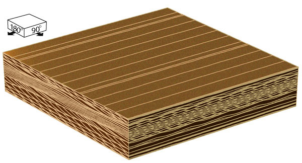
FIG. 79. A sequence of four images showing the structure produced when one set of bedforms is replaced by smaller bedforms with a different trend. Bedforms in the first set become smaller and migrate more slowly, while those in the second set grow larger and migrate faster.
RECOGNITION: All of the preceding computer-generated structures show depositional situations in which the main bedforms are maintained through time. In real flows, however, one set of bedforms can be replaced by another unrelated set. This example shows the structures that are produced when one set of bedforms is replaced by a second set with a different size and trend. Migration of the second set over the first can partially preserve the first set, thereby enabling recognition of the depositional surface and determination of the spacing of the individual ripples (Fig. 6). The structure that is shown here could probably be recognized in well exposed outcrops, because the sequence begins and ends with bedding that is extremely simple (invariable two-dimensional cross-bedding). Where one complex structure is replaced by another, however, the combination may be so complex as to be virtually impossible to interpret.
ORIGIN: This structure results from a change in flow direction. The change in flow direction destroys one set of bedforms and creates another. At the start and end of this sequence, the direction of sediment transport cannot be determined; the bedforms that existed at those times were so two-dimensional that they give no indication of along-crest transport. Throughout the majority of the structure, however, the intersecting bedforms can be used to quantify sediment transport in both along-crest and across-crest directions. Shortly after the start of this sequence, the superimposed bedforms were small and moving slowly (relative to the main bedforms), indicating that the main bedforms were roughly transverse to transport. At the time of the third illustration in this sequence, the second set of bedforms had become larger and were moving faster, and the combination of bedforms and the resulting internal structures resemble examples that were previously shown in steady depositional situations (Fig. 46). A rotation in the transport direction is one mechanism for causing one set of bedforms to become oblique and for eventually causing the creation of a new set of bedforms. Such changes undoubtedly occur in virtually all depositional environments.
