Pacific Coastal and Marine Science Center
Bedform Sedimentology Site—ripples, dunes, and cross-bedding
|
Forecasting Techniques, Underlying Physics, and Applications
5.1 Introduction5.1A. Preview-- Science is based on the principle of repeatability: each time a system experiences similar conditions--both internal to the system and forces exerted externally on the system--we expect the system to exhibit a similar response. Forecasting exploits this principle by using the observed behavior of a system to predict behavior when similar conditions recur. Even if the equations describing a system are unknown, we can nevertheless use forecasting to learn about the system. For some purposes--such as weather forecasting, financial forecasting, or noise reduction--predicting the future is the primary goal of the forecasting. For the purpose of characterizing system dynamics, in contrast, predictions are made in an exploratory manner to learn what kinds of models perform best. For a preview of how the forecasting procedure works, we can consider the Lorenz system described in Chapter 2. Three approaches could be used to predict the future of this system. First, we could measure the initial conditions (nonlinearity of vertical temperature gradient, temperature difference between rising and falling fluid, and intensity of convection) and use the three coupled equations (2.13) to predict the values of the three variables for successive steps in time. A second approach could be employed if the governing equations were unknown, but sequential observations of the system were available. We could use the sequential observations to plot the 3-dimensional attractor, locate each predictee (a point whose three coordinates are given by the three variables that define the state of the system), identify nearby points (or neighbors) on the attractor, and predict the future state of the predictee by tracing the trajectories of the neighbors. For reasons that will be discussed below, this same procedure can be employed on an attractor plotted using three lagged values of one variable rather than using simultaneous values of three variables. The third approach requires even less knowledge about a system than the two outlined above. Even if we had no knowledge about the dimensionality of an attractor, we could perform exploratory computations for a variety of linear and nonlinear models and identify which models yield the most accurate forecasts. In this way we could not only predict the future of the system, but could characterize the system as well. Of course this procedure would have to be carried out computationally, rather than graphically, because there is no way to plot high-dimensional attractors in a two-dimensional image. This third approach forms the basis for the techniques that are discussed in detail below. Although these techniques rely on statistical operations, the underlying principles are rooted in several physical principles that are discussed below: (1) attractor trajectories can not cross (which would require that a system respond differently when identical conditions recur), (2) delay-coordinate embedding can be used to represent initial conditions, and (3) nonlinear relations can be approximated by local linear pieces. 5.1B. Review and terminology of basic concepts-- To those who are unfamiliar with the subject, it may seem contradictory that a system with sinusoidal behavior--and represented with a curved attractor--is purely linear (attractors and techniques for plotting them are discussed in Chapter 2). In this section we will begin by examining the math, physics, and attractor geometry of such a system. These concepts are important, because they provide the basis for understanding the nonlinear prediction methods that follow. An example of a linear system is a mass oscillating on a spring that exerts a compressional or extensional force that varies proportionally with the deformation of the spring. Such a system can be approximated by the equations
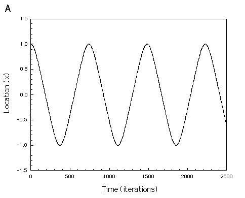
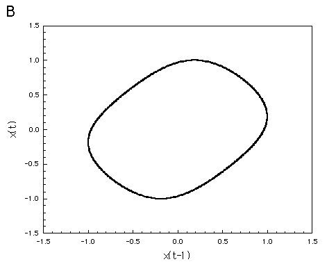
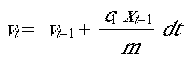
where xt gives the location of the mass as a function of its previous location xt-1 and velocity vt, dt is a short step through time, c1 is a coefficient that relates the force exerted by the spring to its displacement, and m is mass. Equation (5.1) defines the new location as the previous location plus the change in location during time dt. Equation (5.2) defines the new velocity as the previous velocity plus the change in velocity during time dt (rate of change in velocity, or acceleration, is equal to force c1xt-1 divided by mass m). This system is described as linear because the future state of the system (location and velocity) is a linear function of the previous location and velocity. Although the system described by these equations is linear, the time series resulting from repeated iteration of the two equations is sinusoidal, and the attractor (plot of xt vs vt or xt vs xt-1) is curved (Fig. 5.1). Linearity refers to the relation between variables, not to the shape of a plot of the time series or geometry of the attractor.
Figure 5.1 Linear mass-spring system described by equation 5.1. (a) The time series is peroidic and sinusoidal. (b) Attractor illustrated by plotting lagged values of location x. To define the state of this mass-spring system requires two variables: location and velocity. But two sequential values of location provide essentially the same information as simultaneous measurements of location and velocity, because velocity can be determined from the change in location through time; similarly, relative location can be determined from sequential velocities. Thus, the system state is uniquely defined by a combination of two variables (simultaneous location and velocity) or by sequential values of either variable. We can modify equation (5.1) to describe the mass-spring system using two sequential values of location by substituting (xt-1-xt-2)/dt for vt-1 in equation (5.2) and then substituting the right side of equation (5.2) for vt in equation (5.1)
(For more accurate iterative computational techniques, see Lorenz, 1963.) By rearranging terms and combining constants, equation (5.3) can be simplified to
which clearly illustrates the linear property of a sinusoidal time series: each value in the time series is a linear combination of two prior values. One of the uses of forecasting is to evaluate the number of degrees of freedom of a system, which can be defined in at least two ways (Gershenfeld and Weigend, 1994). The number of degrees of freedom can be thought of as the number of variables that may be needed to uniquely define the state of the system mathematically. For example, the mass-spring system described by equation could be described as having two degrees of freedom (x and v in equation 5.1; xt-1 and xt-2 in equation 5.4). The equations have two other terms (c1 and m in equation 5.1; c2 and c3 in equation 5.2b), but, as long as the spring properties and mass do not change, these terms are constant and therefore do not contribute additional degrees of freedom. If, on the other hand, one or both of these terms vary periodically (as in an example discussed later in this chapter), then these terms would contribute addtional degrees of freedom. One might argue that the total number of degrees of freedom of the mass-spring system is greater than 2, but that in the special case where the mass and spring are constant the active number of degrees of freedom is 2. The distinction between active and total degrees of freedom is particularly important for geological systems. For example, the total number of degrees of freedom of a turbulent fluid is nearly infinite (the continuous velocity, pressure, and temperature fields described by the Navier-Stokes equations). The active number of degrees of freedom, which is the number of degrees of freedom that can be evaluated using forecasting, may be considerably less than the total number. In the case of a fluid, for example, adjacent regions of the fluid do not necessarily behave independently. In such a case, the active number of degrees of freedom may be thought of as the velocity, pressure, and temperature for every small eddy having independent (uncorrelated) values from adjacent eddies. The purpose in evaluating the number of degrees of freedom is to learn whether complicated behavior observed for a system arises because the system is complicated (many equations and many variables) or because of nonlinear properties of a simple system (few variables). Equation (5.1) can be modified to describe a nonlinear system by modifying the term representing the force exerted by the spring. For example, force might vary with the cube of the spring's displacement, requiring that c1xt-1 be replaced with c1(xt-1)3(Fig. 5.2). The resulting system is nonlinear rather than linear, because xt is no longer simply a linear function of previous values of x.
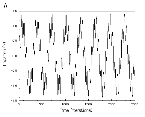
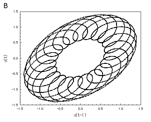
Figure 5.2 Nonlinear mass-spring system described by substituting (x(t-1))3for x(t-1) in equation 5.1. (a) Time series of location x. (b) Attractor illustrated by plotting lagged values of x. Both the linear and nonlinear mass-spring systems are periodic, but other linear and nonlinear systems may be nonperiodic. Nonperiodicity of linear systems is relatively easy to visualize; it originates where a system has so many degrees of freedom that initial conditions are not repeated; such a system is said to be stochastic. Nonperiodicity also can arise from a deterministic process: nonlinearity of the underlying equations can cause the system to exhibit behavior that evolves differently, even where initial conditions are nearly identical (Chapter 2). It is easy to visualize how we might predict the future behavior of a simple periodic system (Fig. 5.1) even in ignorance of the governing equations (5.1-5.2): we could merely use one wavelength of the time series as a template to predict the future, given any initial conditions. Two points are required to define the initial conditions, because all values (except the peak and trough) are encountered twice during each wave period--once during acceleration and once during deceleration; two sequential points distinguish between these two situations. Alternatively, we could make predictions by plotting the attractor in phase space and using the attractor to make predictions. Adding a second periodic component to a time series (Fig. 5.3) may make forecasting too complicated to perform graphically, particularly if the ratio of the two frequencies is not a rational number (quasiperiodicity). In such a case, the difficulty of making predictions is an indication of the limitation of the graphical predictive technique, not an indication that the system is particularly complicated. Such a system is simple (few degrees of freedom), linear, and retains a power spectrum that is diagnostic of periodicity (in this case, power is concentrated in two frequencies). The forecasting becomes more complicated for two reasons: (1) the relative phase of the two components may vary through time, causing the long-period cycles to differ from one to the next (either never repeating--as in the case of quasiperiodicity--or repeating after multiple cycles), and (2) the attractor dimension increases to three, making it difficult to represent clearly on a two-dimensional page. The techniques presented in the following section are designed for forecasting in more complex systems with multiple frequency components (higher attractor dimension), noise, nonlinearity, and with external forces that vary through time.
Figure 5.3 Plots of a two-frequency linear system. (a) Time series. (b) The attractor has the 3-dimensional shape of a torus; this image is the projection onto a plane. Continue to next section.
|

 (5.2)
(5.2)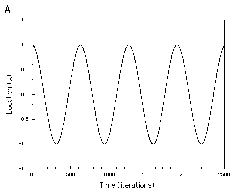
 (5.3)
(5.3)