Woods Hole Science Center
Sea-Floor Character and Sedimentary Processes in the Vicinity of Woods Hole, Massachusetts
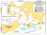
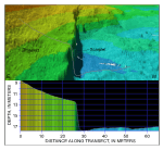
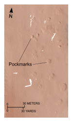
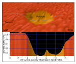
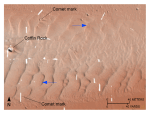
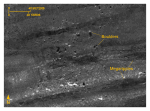
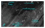
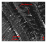
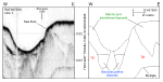
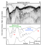
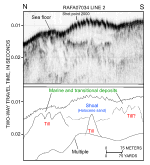
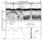
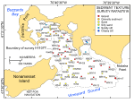
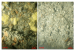
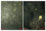
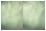
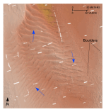
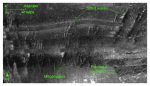
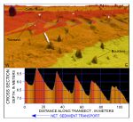
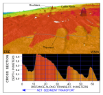
Surficial Sediments Gravel, including boulders, is present in the shallow waters along the coastline near Nobska and Juniper Points, around Grassy and Devils Foot Islands, in the constricted Broadway and Woods Hole passages, in those parts of Vineyard Sound where the Holocene section is thin or absent, and on isolated bathymetric highs, such as Great Ledge (fig. 18, 33). These coarse deposits are primarily associated with outcrops of glacial drift, and are probably lag deposits of the till that is exposed onshore in the Buzzards Bay moraine. Bottom video shows that small, scattered patches of sand are found locally among the boulders. Aprons of gravelly sand, which commonly armor finer grained underlying sediments, locally surround the gravel areas. Sand is the dominant sediment textural class on Nonamessset Shoal and in the sand-wave fields around Great Ledge and along the southwestern part of the study area (fig. 33). The sand in the sand-wave fields is typically medium- to coarse-grained, moderately well sorted, and finely skewed. Elsewhere, the sand is restricted to smaller areas and is generally medium- to fine-grained and poorly sorted. Silty sand, sandy silt, and clayey silt form a textural progression of increasing mud content and decreasing benthic environmental energy. These sediment types are found in the more protected areas at the northern ends of Little and Inner Harbors. Sedimentary Environments Four distinct sedimentary environments are present within the study area and include areas of the sea floor characterized by erosion or nondeposition, coarse-bedload transport, sorting and reworking, and deposition. Environments characterized by erosion or nondeposition, which reflect high-energy conditions (Knebel and Poppe, 2000), prevail in exposed, relatively shallow waters. These conditions are present around Grassy and Devils Foot Islands, along shorelines such as off Juniper and Nobska Points, in constricted channels such as Broadway and Woods Hole, and on isolated bathymetric highs such as Great and Red Ledges. Strong tidal currents and wind-driven waves prevent the deposition of Holocene marine sediments and erode the finer fraction from the sea-floor sediments, leaving exposed lag deposits of boulders and gravel (fig. 18). Seaweed, sponges, soft corals, mussels, barnacles, and other sessile fauna and flora obscure the rock surfaces (figs. 34, 35). As water depth increases, the strength of storm and tidal currents at the sea floor decreases. Conditions favoring erosion or nondeposition are replaced by sedimentary environments characterized by coarse-bedload transport. This environment, which is defined by sand waves and megaripples, is prevalent across the southern part of the study area in Vineyard Sound and on shoals that extend both eastward and westward from Great Ledge (fig. 18). The sediments are predominantly moderately well sorted sand; ripples are ubiquitous on the sand-wave and megaripple surfaces (fig. 36). Shell debris is concentrated in the troughs of the bedforms; moon snails and sand dollars are common in the bottom video. The sea floor near the entrances to and in the shallower parts of Little and Inner Harbors and shoreward of Nonamesset Shoal are more protected from wind- and tidally driven currents. Sedimentary environments here are primarily characterized by processes associated with sediment sorting or reworking. Faint current ripples observed on the surface of grab samples of muddy sands, sediment resuspension observed in bottom video, and eelgrass beds and shell accumulations reflect these processes (fig. 37). The sea floor at the northern, most protected parts of Little and Inner Harbors is characterized by low backscatter on the sidescan-sonar mosaic and predominant long-term deposition (fig. 27). In these areas, fine-grained sediments accumulate in the low-energy environments protected from strong tidal and storm conditions. Amphipod and polychaete tubes, shrimp burrows, organic debris, and snail and crab tracks are locally common in these muddy sediments (fig. 38). Moraine Unstratified glacial drift, which typically forms acoustic basement on the subbottom seismic profiles, has an irregular, abrupt upper surface (fig. 29). These deposits underlie most of the study area and are exposed along shorelines as bouldery lags of the original till, on isolated bathymetric highs, and in channels and passages where the tidal currents are strong and Holocene sediments thin (figs. 18, 20, 26, 39, 40). Onshore, this drift has been mapped as a segment of the Buzzards Bay moraine (Oldale and Barlow, 1986; Oldale, 2001). The multibeam, sidescan-sonar, and sub-bottom data presented herein show that these onshore moraine deposits continue offshore under the present study area. In addition to the many small (1 to 2 m) elevations interpreted to be boulders, several relatively steep-sided, isolated depressions are also scattered on the moraine surface. Although they are now primarily maintained by scour associated with the strong tidal currents, we believe these rounded depressions were originally kettle holes, formed by the melting of detached blocks of stagnant ice that were partially buried in the glacial drift. A seismic facies characterized by finely laminated, rhythmic, parallel internal reflectors that drape the underlying topography is found within some of the depressions (fig. 29). From their seismic character, we interpret these deposits to be varved, muddy, glaciolacustrine sediments that record deposition in the kettle-hole lakes. Sand Waves Transverse and barchanoid sand waves, and their derivative forms, are present in the study area (fig. 18). The transverse bedforms, which exhibit an almost continuous spectrum of amplitudes and crestline lengths, dominate on the shoals east and west of Great Ledge, in the sand-wave field in the southwestern part of the study area, and are found elsewhere in small isolated fields (figs. 25, 28, 41). Current ripples occur on the flanks of the megaripples, megaripples occur on the flanks of sand waves, and sand waves occur on the flanks of larger sand waves (figs. 36, 42). Many of the transverse sand waves exceed 200 m in length, but none are longer than 300 m. Amplitudes of the transverse waves commonly exceed 1 m, but those of only a few of the larger waves exceed 2 m. Together, the transverse and barchanoid sand waves reflect the strength of the bottom currents and can be used to indicate directions of net sediment transport (Ludwick, 1972; Allen, 1980). Wave-crest morphology is variable and waves with relatively straight, smoothly sinuous, undulating, curved, and bifurcating crest forms are present within the sand-wave fields. Borders of sand-wave fields can be abrupt, and bifurcation of the wave crests, where present, is most common near abrupt edges of the fields (fig. 25). The presence of this crest morphology at these locations is to be expected because bifurcation of wave crests indicates transitional flow conditions and the development of secondary flows (Aliotta and Perillo, 1987). The crest of a sand wave may bifurcate if the forces of tidal oscillation do not remain equal along its entire length, especially if the contact between flow cells is sharp or if differences in flow rate or direction are great. Where transverse sand waves are present in the study area, asymmetry of the bedforms is typically pronounced, suggesting a flow-transverse crest orientation and slip faces that are oriented toward the direction of net sediment transport. On the shoal east of Great Ledge, slip faces of the sand waves along the northern edge of the shoal are oriented toward the east, but those along the southern edge are oriented toward the west (figs. 25, 43, 44). Sand-wave asymmetry on the opposite sides of the shoal in the channel west of Great Ledge similarly reverses orientation. Slip faces of the sand waves along the western edge of the shoal there are oriented toward the north, but those along the eastern edge are oriented toward the south (figs. 41, 45, 46). This configuration suggests that the sand is transported in clockwise gyres that shape and maintain both shoals. Also, sand-wave morphology in both shoals becomes more symmetrical and disorganized toward the center of the fields. Slip faces in the sand-wave field south of Nonamesset Shoal are oriented toward the west (fig. 47). This asymmetry indicates a net westward sediment transport. Megaripples, which are commonly present on the stoss slopes and between the transverse sand waves, typically mimic the asymmetry of the sand waves, but not necessarily their orientation. For example, sand-wave crests in the south-central part of the study area trend 20° to 30°, but megaripple crests trend roughly 10° to 20° (fig. 42). The presence of megaripples with crests oblique to trends of the underlying sand waves is evidence for flow separation and increased turbulence, which can promote increased sediment flux from the development of secondary flows (Allen, 1968). Whether the difference in orientation of sand waves and megaripples is caused by variance in sediment transport directions or propagation time scales is uncertain. Barchanoid sand waves occur in the southeastern part of the study area where Holocene sediments are thin and discontinuous (fig. 48). These waves commonly align into elongate fields, with smaller isolated waves concentrated in the eastern ends. Wavelengths increase westward within the barchanoid wave fields, the fields widen, and the barchanoid waves become larger and coalesce into complex forms and highly curved ridges. Individual barchanoid sand waves average about 20 m in width, but complex coalesced forms can exceed 60 m. In places, barchanoid waves grade laterally into transverse morphologies. The sea floor on the concave side of the barchanoid wave troughs is relatively smooth, but the stoss slopes are typically covered in megaripples, especially near the "horns" of these waves. Relief of the barchanoid waves is typically about 1 m. However, linear scour depressions, which cut into the underlying deposits and are probably formed by roll vortexes, commonly exist in the troughs within the convex areas of the larger barchanoid waves. If trough-to-crest amplitudes are measured from these depressions, the waves appear slightly (0.2-0.5 m) larger. The presence of “blow-out” depressions is evidence for more intense scour on the down-current sides of the barchanoid sand waves. Although similar in morphology, the barchanoid waves described here are much smaller that those reported elsewhere off southeastern New England (Poppe and others 2007a; Poppe and others, 2007b). Regardless of size, location, and complexity, all of the barchanoid sand waves are concave westward, indicating net westward sediment transport (McKee, 1966; Cacchione and others, 1987). Asymmetry of megaripples on the stoss slopes of the barchanoid sand waves, of adjacent transverse sand waves, and of scour marks around nearby boulders also indicates net westward transport in the southeastern part of the study area. The abundance and amplitude of transverse and barchanoid sand waves reflect the action of strong bottom currents in this part of Vineyard Sound. The presence of current ripples and megaripples on these sand waves and the steepness of the slip faces suggest that this transport is active and that the sand waves are propagating under the present hydraulic regime (Dalrymple and others, 1978; Reineck and Singh, 1980; Allen, 1982). Although current ripples may reverse their orientation during semidiurnal tidal cycles because of the small volume of the ripples, no reversal in either the sand-wave or megaripple morphology or orientation was observed in the multibeam or sidescan-sonar data of adjacent lines collected at different tidal stages. Whether this tidal independence of large bedform orientation is due to the spatial distribution of residual currents, or to an asymmetry of current velocities is also uncertain, but it does suggest that the larger bedforms are more stable and move over longer time scales than the smaller bedforms. Scour Features Intensity of the tidal-current scour is also evidenced by depressions around obstructions that are visible in the bathymetric data. Swirling currents develop around boulders that protrude through surficial sediments. Turbulence causes increased flow velocity sufficient to scour the sea floor downstream from obstructions and to produce coarse-sediment-floored depressions that taper away from the obstruction. Good examples of these bedforms, known as comet marks or obstacle marks, are present around boulders along the northern and southern edges of the sand-wave field east of Great Ledge (figs. 25, 48). Obstacle-mark asymmetry around these boulders indicates net sediment transport is toward the east north of this sand-wave field and toward the west farther offshore, south of the field. Tidal Deltas Large, elongate accumulations of sediment are present at the eastern ends of both the Broadway and Woods Hole Passages (figs. 18, 49, 50). The sediment is primarily sandy gravel, but shell beds are common (fig. 51). These features are widest and thickest near the mouths of the passages, but progressively thin and narrow eastward (fig. 52). We believe that these accumulations developed as ebb-tidal deltas, constructed from finer grained sediments winnowed from the seabed within the passages and from mussel-shell debris. Deflections in the distal parts of the deltas suggest that net transport of the finest grained sediment is eventually southward toward Vineyard Sound. Although the area is not included in this study, a similar tidal delta is probably also present at the western end of the Woods Hole Passage. Marsh Deposits The steep, near-vertical scarplet at the edge of Parker Flat was formed by intense erosion by the strong flood-tidal current emerging from the eastern end of the Woods Hole Passage and the dense, cohesive sediments that form the substrate of this feature (figs. 18, 22, 50, 53). This scarplet, whose relief in places exceeds 5.5 m, extends for a distance of more than 130 m. A talus pile of boulders at the base of the scarplet also suggests that the surrounding drift has been removed by erosion. The sediment composing the substrate is a dark olive gray silty sand with a high organic content (fig. 54). Much of the particulate organic matter is fibrous and three CHN analyses yielded total organic carbon contents of 16.81, 6.47, and 9.72 percent. Small (5-15 mm in diameter), rounded, elongate cavities in the surface of this deposit are related to bio-erosion, and boring mussels were common in the samples. On the basis of the deposit's high organic content and location, we believe that this deposit is the remnant of a tidal marsh, which probably accumulated during the Holocene rise in sea level. Although not directly measured, the thickness of this marsh deposit is at least 5.5 m, as determined from the relief of the scarplet. However, the presence of outcrops of this deposit on the slope above the scarplet and the absence of a lower contact with exposed underlying sediment suggest that it is thicker. Pockmarks We have interpreted the depressions at the northern end of Little Harbor to be pockmarks formed by the release of biogenic methane (figs. 18, 23, 24). This interpretation is based on the presence of gas observed in the subbottom seismic profiles (fig. 32), the smell of hydrogen sulfide in the sediments from this area, and the likely presence of buried marsh deposits inferred from the presence of exposed deposits elsewhere in this study area (fig. 18). The cause of the varied size and morphology of these features, although uncertain, may be related to their age, to the volume of gas released, or to the rate of release. Anchor Scars Scars caused by anchors or mooring chain dragging across the seabed are recorded by high-backscatter lines in the sidescan-sonar mosaic that range up to about 30 m in length (fig. 27). The scars, which are concentrated in the northern part of the Inner Harbor, owe their occurrence within this area to numerous moorings located there and to vessels seeking shelter in the lee of Penzance Point during storms. Shipwrecks Five shipwrecks have been identified in the study area, all within the Inner Harbor (figs. 18, 55). The smallest has a pointed bow and lies in about 10 m of water along the northern edge of the study area. The remaining wrecks lie at the bottom of the 22-m-deep depression within this harbor. Two have a blocky, rectangular appearance, suggesting that they are barges; the other two are a fishing vessel and the remains of a lifeboat. Sand Resources Much of the economy of Cape Cod, Massachusetts, is dependent on the tourist industry, and much of the tourist industry is dependent on the quality of the local beaches. These beaches have been eroding and their shore faces have become steeper and rockier. These changes, which have degraded the character of the beaches and made them potential candidates for beach-nourishment projects, are attributable to the collective action of storms, sea-level rise, and pervasive man-made coastal alterations. Although there are no current offshore aggregate mining activities in Massachusetts because nearly all coastal waters are protected by the Ocean Sanctuaries Law (Giordano, 1993), beach-replenishment projects have been conducted where the aggregate was derived from material resulting from maintenance dredging of navigation channels. Within the study area, shoals flank the eastern and western sides of Great Ledge (fig. 56). If removed by dredging during harbor management activities, these sand bodies could offer high-quality sand for beach nourishment and shoreline restoration. Although the ebb-tidal deltas associated with the Broadway and Woods Hole Passages also contain substantial volumes of sediment, the gravelly texture and high shell content make them less desirable resource targets. The U.S. Army Corps of Engineers is presently studying the feasibility of dredging the channel leading into Great Harbor to provide access to Woods Hole port facilities for larger ships. As part of this project, the shoal west of Great Ledge would be dredged. Vibracores from stations C and M on the shoal (fig. 56), collected in preparation for this project (Robert Taylor, TG&B Marine, written commun., 2007), confirm our surficial textural analyses and show that clean sand continues to a depth of at least 2.4 m into the sediment. Cores collected from off the shoal on the surrounding sea floor (for example, station B; fig. 56) show that gravel and silt contents there increase with depth into the sediment, indicating that volumes of clean, moderately well sorted sand are limited to the shoals. Although interpretations of subbottom seismic profiles collected as part of our present study show that the Holocene section thickens and fills a depression on the surface of the glacial drift beneath the shoal west of Great Ledge (figs. 30, 31), exploitable sand is probably limited to that portion of the shoal that extends above the surrounding sea floor. Volume of this upper part of the shoal was estimated by calculating the area of the shoal (about 630 m²) and projecting the surrounding sea floor as a plane beneath the shoal (fig. 56). This plane was assumed to be flat and to dip gently, but progressively, northward. Gridded bathymetry and calculated depths to the plane were used to determine thickness of the overlying sediment at 34 representative locations. These values were averaged and, along with the shoal area, used to calculate an 1,100-m³ volume of potentially exploitable aggregate. |
Click on figures for larger images.
|