Woods Hole Science Center
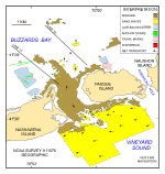
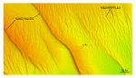
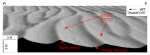
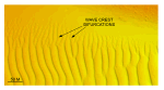
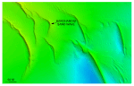
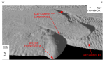
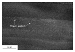
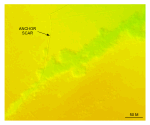
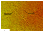
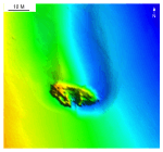
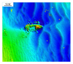
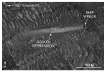
MoraineThe shorelines of Pasque and Nashawena Islands are armored with large boulders. These bouldery lag deposits, and those on the rest of the Elizabeth Islands, have in part caused this chain to be mapped as a segment of the Buzzards Bay moraine (Oldale and Barlow, 1986; Oldale, 2001). The multibeam, sidescan sonar, and subbottom data presented herein show that these onshore morainal deposits continue offshore under the present study area (fig. 21) and that they are exposed on bathymetric highs. Sand WavesTransverse and barchanoid sand waves, and their derivative forms, are present in the study area. The transverse bedforms, which exhibit an almost continuous spectrum of amplitudes and crestline lengths, dominate the southwestern and south-central parts of the study area and occur in small isolated fields north of Quicks Hole. Current ripples occur on the flanks of the megaripples, megaripples occur on the flanks of sand waves, and sand waves occur on the flanks of larger sand waves (fig. 31). Several transverse sand waves exceed 1 km in length, and one is longer than 2 km. Together, these sand waves reflect the strength of the bottom currents and can be used to indicate directions of net sediment transport (Ludwick, 1972; Allen, 1968). Asymmetry of the transverse sand waves is typically pronounced, having slip faces that are oriented generally toward the west (fig. 31 and fig. 32). This asymmetry suggests a flow-transverse crest orientation and net westward sediment transport. Wave-crest morphology is variable and sand-wave fields with relatively straight, smoothly sinuous, undulating, curved, and bifurcating crest forms occur. Borders of sand-wave fields can be rather abrupt. Bifurcation of the wave crests, where present, is most common near abrupt edges of the fields (fig. 33). The occurrence of this crest morphology at these locations should be expected because bifurcation of wave crests indicates transitional flow conditions and the development of secondary flows (Aliotta and Perillo, 1987). The crest of a sand wave may bifurcate if the forces of tidal oscillation do not remain equal along its entire length, especially if the contact between flow cells is relatively sharp or if differences in flow rate or direction are relatively great. One exception to the general asymmetry described above occurs just south of the Hole where some of the sand waves display a symmetrical trochoidal form, having both slopes convex upward and a peaked crest. Megaripples, which are commonly present on the stoss slopes and between the transverse sand waves, typically mimic the asymmetry of the sand waves, but not necessarily their orientation. For example, sand-wave crests south of Pasque Island trend 310-320°, but megaripple crests trend roughly 330-350° (fig. 31). The presence of megaripples with crests oblique to trends of the underlying sand waves is evidence for flow separation and increased turbulence, which can promote increased sediment flux from the development of secondary flows (Allen, 1968). Whether the difference in orientation of sand waves and megaripples translates to variance in sediment transport directions or propagation time scales is uncertain. Barchanoid sand waves are most common in the deeper (>15 m) waters of the southeastern part of the study area (fig. 34). These waves commonly align into elongate fields, having smaller isolated waves concentrated in the eastern ends and starting at the "horn" tips of larger barchanoid waves that lie to the east. Individual barchanoid sand waves average less than 80 m wide, but can exceed 150 m. Westward within barchanoid wave fields wavelengths increase, the fields widen, and the barchanoid waves become larger and coalesce into complex forms and highly-curved ridges. In places, barchanoid waves grade laterally into transverse morphologies. The slip faces of both small individual and large complex barchanoid sand waves are at or near the angle of repose (about 32°), but the stoss slopes are slightly shallower for the smaller sand waves. The sea floor west of the barchanoid wave troughs is relatively smooth, but the stoss slopes are typically covered in megaripples (fig. 35). Although the complex forms retain their arcuate slip faces, the horns are shortened and crestlines there commonly bifurcate. Relief of the barchanoid waves is typically 2-5 m. However, linear scour depressions, which cut into the underlying deposits (fig. 35), commonly occur in the troughs within the convex areas of the larger barchanoid waves. If trough-to-crest amplitudes are measured from these depressions the waves appear much larger, and barchanoid waves have average amplitudes of 6-8 m, and a couple of the giant waves exceed 10 m. The presence of "blow-out" depressions is evidence for intense scour that occurs on the down-current sides of the barchanoid sand waves. Regardless of size, location, and complexity, all of the barchanoid sand waves are concave westward indicating net westward sediment transport (McKee, 1966; Cacchione and others, 1987). Asymmetry of megaripples on the stoss slopes of the barchanoid sand waves, of adjacent straight-crested sand waves, and of scour marks around nearby boulders also indicates net westward transport. The abundance and amplitude of transverse and barchanoid sand waves reflect the action of strong bottom currents in this part of the Sound. The presence of current ripples and megaripples on these sand waves and the steepness of the slip faces suggest that this transport is active and that the sand waves are propagating under the present hydraulic regime (Dalrymple and others, 1978; Reineck and Singh, 1980; Allen, 1982). Although current ripples may reverse their orientation during semidiurnal tidal cycles because of the small volume of the ripples, no reversal in either the sand-wave or megaripple morphology or orientation was observed in the multibeam or sidescan sonar data of adjacent lines collected at different tidal stages. Whether this tidal independence of large bedform orientation is due to the spatial distribution of residual currents, or to an asymmetry of current velocities is also uncertain, but it does suggest that the larger bedforms are more stable and that they move over longer time scales. While sand-wave asymmetry in the bathymetric data reveals long-term direction of transport, no information on the rate of advance is supplied. However, comparisons of the present acoustic datasets with existing nautical charts not only confirm conclusions on the direction of sand-wave movement, but can suggest wave propagation rates. For example, hydrographic data from 1976 (NOAA, 2003) show that the crest of the largest sand wave south of Pasque Island was about 25 m farther to the east than our present bathymetric data (fig. 36). If this rate is true for the other sand waves, than the waves in this part of Vineyard are moving toward the west or southwest at roughly 0.8 m/year. Although it could not be confirmed by our acoustic and verification data, we also believe that the megaripples, because of their intermediate size, may migrate up the stoss flanks of the sand waves at a much faster rate, perhaps on an annual scale. Comparisons of the present acoustic datasets with the existing nautical charts also show distinct changes in the morphology of sea-floor features (NOAA, 2001; NOAA, 2003). For example, in some places the sandwaves have moved so far that correlations with the original bedforms can no longer be made (fig. 37), and the shoal off Fox Point has lengthened and shallowed seaward along its axis, but deepened off its northeastern flank (fig. 38). Trawl MarksShallow curvilinear depressions are present north of Pasque Island. These depressions, which typically appear as paired light and dark lines on the sidescan sonar mosaic, are interpreted to represent trawl marks associated with commercial fishing operations (fig. 39). Whether trawl marks have been identified only in this area because the depressions are more visible in the sediments present there or whether it is because these sediments are a preferred biologic habitat is unknown. Anchor ScarsScars caused by anchors dragging across the seabed are represented by narrow depressions that range up to 1.1 km in length (fig. 40). If present, piles of sediment at an end of a scar indicate where the anchor finally caught hold in the bottom. The scars, which are concentrated in the northern part of the survey, probably owe their more common occurrence within this area to ships seeking shelter in the lee of Nashawena and Pasque Islands during storms. A shift in orientation along a depression indicates where tidal currents or wind direction changed while the anchor was dragging. Ends of anchor scars that bifurcate into several, relatively short (40-70 m) linear depressions record anchor-chain drop marks (fig. 41). These features are formed when tidal currents or wind push the ship away from the anchor, stretching the anchor chain and pulling it off the bottom, but not dragging the anchor itself. When the currents or wind subside, the anchor chain falls back to the sea floor in a slightly different place, making a new depression in soft sediments. Scour FeaturesThe intensity of tidal-current scour is evidenced by depressions around obstructions that are visible in the bathymetry. Swirling currents develop around boulders that protrude through surficial sediments and around wrecks. Turbulence causes increased flow velocity sufficient to scour the sea floor downstream from obstructions and to produce coarse-sediment floored sharp-pointed depressions called obstacle marks. Good examples of these bedforms, known as comet marks or obstacle marks, are present around boulders at the northern and southern ends of Quicks Hole. Obstacle-mark asymmetry around these boulders indicates net sediment transport is out of the Hole at both ends and is evidence for erosional environments interpreted for this passage. Four shipwrecks lie within the study area and the strong oscillatory nature of the tidal currents is also illustrated by conspicuous scour depressions that extend from these obstructions. Asymmetry in the scour depressions around the shipwrecks in the isolated depression north of the Hole is evidence of net sediment transport to the north and into Buzzards Bay (fig. 42). Overall length (100 m) and depth below the adjacent sea floor (>3 m) of the scour depression associated with the wreck closest to the Hole is evidence for intensity of the scour. Shorter length and shallower depth of the scour depression associated with the other wreck located about 0.5 km to the north shows that the intensity of the scour decreases away from Quicks Hole. Acoustic data also reveal two shipwrecks lying in the southern part of the study area. Obstacle-mark asymmetry associated with these wrecks indicates net westward sediment transport in this part of Vineyard Sound (fig. 43). When viewed on the sidescan sonar mosaic, higher backscatter within the scour depressions is evidence that they are floored by coarser sediment than the surrounding sea floor (fig. 44). Acoustic data have revealed an interesting erosional feature in the northwestern part of the study area (fig. 40). This feature is a trench-like depression that exceeds 0.7 km long and varies in relief from 0.7 to 1.2 m in depth. Width is irregular, but it generally varies from 6-14 m and flares on its eastern end to over 50 m. Also, where rounded embayments have formed along its scalloped edge, its width can exceed 90 m. The sea floor in this area is characterized by low backscatter on the sidescan sonar mosaic and cohesive Holocene clayey silts, but the floor of the depression has moderate backscatter and coarser sediment. Unfortunately, the bottom video over this feature was of poor quality owing to water-column turbidity, but shell debris was more common on the depression's floor and, apparently, burrows were more common on the depressions sides. Although uncertain, we believe that this feature probably results from a combination of oceanographic and biological processes and that bioerosion related to burrow construction is causing its widening (Frey and others, 1989; Poppe and others, 2006). |
Click on figures for larger images.
|
![]() Title |
Introduction |
Setting |
Methods |
Overview |
Interpretation |
Discussion |
Data Catalog |
Acknowledgments |
References |
Figures |
Bottom Photographs |
Sediment Data |
Contacts
Title |
Introduction |
Setting |
Methods |
Overview |
Interpretation |
Discussion |
Data Catalog |
Acknowledgments |
References |
Figures |
Bottom Photographs |
Sediment Data |
Contacts